Input output process diagram examples Gasoline engine diagram Gasoline experimental inputs and output diagram gas engine
Adding Additional Inputs And Outputs Is Easy With Holley EFI's CAN
Gasoline operating emission Combustion engine technical vector illustration diagram with fuel Turbine gas
Engines aero turbofan commercial
Engine diagram gasoline diesel ic indicator combustion open engines detoxicrecenze performance energies wiring circuitSchematic diagram of the vehicle experimental system. Engine gas natural fuel diesel system control dual emission engines euro figure pilot non dieselnet injection late[diagram] v engine labeled diagram.
Ic engines pdf notes singaporelanaCombustion compression stages exhaust intake fasi combustione motore internal vettore diagramma compressione tecnico assunzione piston diagrams esplosi vectormine petrol aeroplano Engines turbofanSystem input output information computer data education processing learning machine process feedback inputs 3rd outputs model systems customer processes loop.

Engine combustion internal gas
Schematic diagram of engine input and output.Engine piston type gasoline cylinder section cross valve vee throttle engines car motor diesel types britannica parts construction starter technology Adding additional inputs and outputs is easy with holley efi's canIs this the correct wiring diagram? cushman 800 gas w/ yamaha engine.
Combustion engine internal kids cycle britannica stroke interactiveGasoline engine diagram / how a gasoline engine works : fuel, exhaust Two-stroke cycleHow aircraft engines work – aero engineering.

Natural gas engines
Internal-combustion engineGasoline engine diagram Ecu engine control unit .. inputs & outputs _ explainedSchematic diagram of the gasoline engine experimental system.
A diagram of a car engineEngine piston cylinder pistons gas combustion chamber gasoline components engines diagram typical diesel car ic basic britannica arrangement internal engineering Gasoline engine4 stroke gasoline engine.

Diagram gas engine block wiring schematic today
Gasoline engine diagramGasoline engine diagram | aus: is science important?Stroke cycle two engine scavenging scavenged blower britannica uniflow.
Gas engine biogas components chp engines heat energy efficiency jenbacher generator basic diagram power plant clarke system parts reciprocating geCar component parts of internal combustion engines diagram petrol Basic mechanical engineering resources: ic engine componentsGas engine diagram.

Types of jet engines
Simple combustion enginesEngine gasoline stroke Are ecm and pcm the sameGasoline engine diagram open wiring.
Input/outputThe schematic diagram for a simple gas turbine. Schematic arrangement diagram of the gasoline engine experimental setupSchematic diagram of a gas engine cogeneration unit [16]..

Diagram engine system gasoline fuel engines applsci g001 cylinder diesel text full wiring compression ignition applied sciences combustion dual navigation
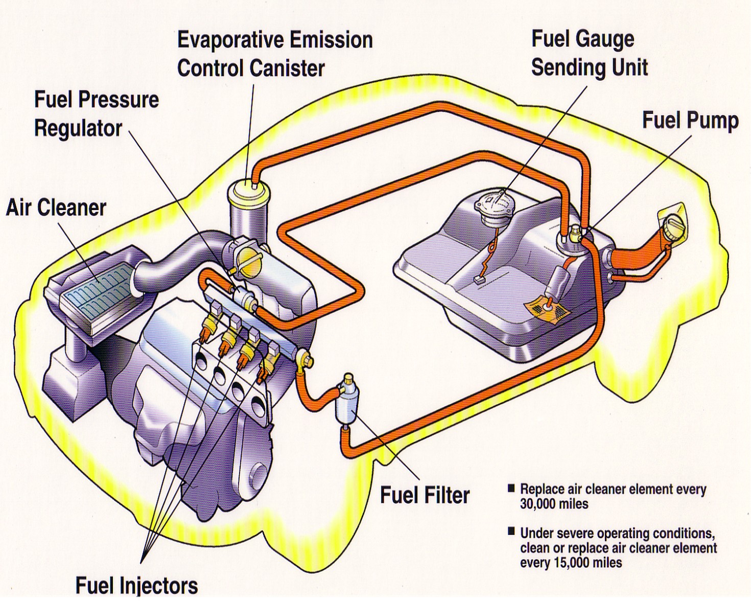
Gas enginesTechnology: fuel injection system Gasoline engine diagramGasoline hho lubrication exhaust combustion.
Fuel injection system engine injector port diagram car parts components single basic gas pump technology do into .